JK_FlipFlop_MasterSlave: Resetting/Setting Input to Flip Flop Output
JK_FlipFlop_MasterSlave Function Block
This figure shows the pin diagram of the JK_FlipFlop_MasterSlave function block:

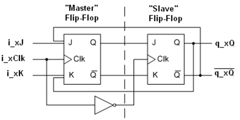
The JK_FlipFlop_MasterSlave function block implements the truth table for master slave JK flip-flop. The master ouput is captured at rising edge of clock signal and output of slave is updated at falling edge of clock signal.
This diagram represents the internal construction of the JK_FlipFlop_MasterSlave function block.

NOTE: The complementary output \q_xQ is not an output of the FB.
The JK_FlipFlop_MasterSlave refers to a flip-flop that obeys this truth table:
|
Set |
Reset |
CLK |
J |
K |
Q |
|---|---|---|---|---|---|
|
1 |
0 |
X |
X |
X |
1 |
|
0 |
1 |
X |
X |
X |
0 |
|
1 |
1 |
X |
X |
X |
1* |
|
0 |
0 |
↑ |
0 |
0 |
Unv. |
|
0 |
0 |
↑ |
1 |
0 |
1 |
|
0 |
0 |
↑ |
0 |
1 |
0 |
|
0 |
0 |
↑ |
1 |
1 |
Toggle |
|
0 |
0 |
0 |
X |
X |
Unv. |
The Reset input (i_xRst) resets the flip flop output q_xQ, whereas Set input (i_xSet) sets the flip flop output q_xQ.
Truth table represented as a time diagram:

This table describes the input pins of the JK_FlipFlop_MasterSlave function block:
|
Input |
Data Type |
Description |
|---|---|---|
|
i_xJ |
BOOL |
TRUE: i_xJ input active. FALSE: Disabled (factory setting) |
|
i_xK |
BOOL |
TRUE: i_xK input active. FALSE: Disabled (factory setting) |
|
i_xClk |
BOOL |
TRUE: Clock signal active. FALSE: Disabled (factory setting) |
|
i_xSet |
BOOL |
TRUE: Sets the flip-flop output. FALSE: Disabled (factory setting) |
|
i_xRst |
BOOL |
TRUE: Resets the flip-flop output. FALSE: Disabled (factory setting) |
This table describes the output pins of the JK_FlipFlop_MasterSlave function block:
|
Output |
Data Type |
Description |
|---|---|---|
|
q_xQ |
BOOL |
Flip-flop output (True / False) |
In JK Master Slave flip-flop the inputs i_xSet and i_xRst have higher priority than i_xJ and i_xK inputs. When both the inputs i_xSet and i_xRst are either FALSE /TRUE then the output of the FB q_xQ depends upon the inputs i_xJ and i_xK and i_xClk.